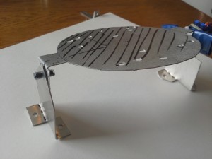
Platform Creation Instructions
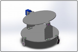
This graphic can be used for reference.
-Pink areas use pipe and tube for fastening
-Green areas use nuts and bolts for fastening
1. Platform Assembly
**Note, be extremely careful with servo motors. Servo motor arms are
not meant to be moved manually and can cause the motor to break! We
have limited replacements.**
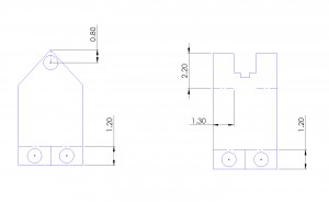
Click on the images for a more precise view of measurements.
(all measurements in centimeters)
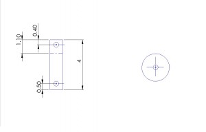
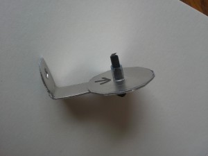
Arms –
- Punch holes in the shown areas, as close to center as possible.
- Cut up vertically between bottom holes on line shown up to 1.2 cm.
- Bend each “foot” 90 degrees in opposite directions.
- On the right arm shown, cut the 1.3 cm long horizontal lines on either side.
- Bend the flaps around to fit tightly to a servo motor.
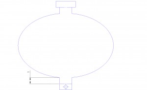
Top Platform –
- Cut hole where shown .5 centimeters up from the bottom edge.
- Bend 90 degrees at both lines.
Legs –
- Cut holes where shown.
- Make 90 degree bend at the line.
- Attach wheel with ABC pip and tubing as shown.
Bottom Platform –
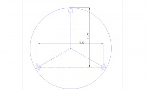
- Make marks at measured locations so that legs can be equally spaced out.
- Do not cut holes in bottom platform as shown, this is just their approximate location.
- Line the legs up with the evenly spaced marks, create additional marks where the holes for the legs need to go by lining up the hole where you want it to go, making a mark, then cutting with the hole punch.
Assembly –
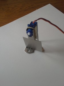
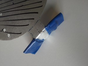
- Fix servo motor arm to the side of the top platform with blue tape as shown below.
- Attach servo to “right” arm by wedging tightly between the flaps, and steadying with a rubber band.
- Attach “left” arm to the top platform with ABC piping and tubing
- Line the arm’s “foot” holes up on the bottom platform and make marks to cut with hole punch.
- After cutting holes in the bottom platform, attach everything to the bottom platform with screws to make
it look like the 3 dimensional depiction.
Your platform is now complete! Hold on to one per group of 4 to make move in the next lab.
2. Servo Motor and Joystick Control.
- Servo motor 1. should already be attached as an arm to complete the top platform.
- Attach the servo motor 2.’s arm to the center of the bottom platform with electric tape.
- Fix the servo motor 2.’s base to the table with electric tape, then attach the arm (and bottom platform) to the base.
**Note you may have to put spacers underneath the servo motor base to make it fit properly.
If there is not enough space you may have to adjust your legs.** - When assembled the lower servo motor should be attached to both the table and the platform with no space in between.
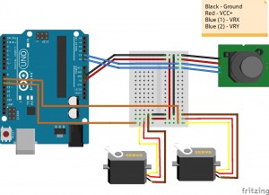 <–[Click for detailed schematic]
-
Pins used on arduino: Digital pins 9, 10; Analog pins 0, 1; 5v Out; Grnd
Use the following code to make this schematic work.
A Brief Explanation of the Code
The first section is all of the variable declaration.
- x_axis / y_axis are the analog input pins for the potentiometer readings on the joystick.
- current_x / current_y are variables to store the potentiometer input and determine whether to increment position up or down.
- x_posit / y_posit represent the current position the motor is actually in and are used to set the position.
- #include <Servo.h> is a library used to bring in another set of commands specifically created to control the servo motors.
- myservo_x / myservo_y are specially created servo objects to control and move the servo motors
The setup section initializes all of the pins that are going to be used.
- Pins 9 and 10 are used to control the servo motor.
- The serial monitor is engaged if you would like to debug the readings from the joystick.
The loop section is the main area where the program is executed in an infinite loop.
- The program reads the current values that are being represented on the joystick in both x and y directions.
- Afterwards there is a number of conditionals that relate to joystick positions and motor positions to determine how to incrementally move the motor.
- You can use these conditions to make the joystick more/less sensitive and also increase/decrease your range of motion.
- If a condition is met, the motor position is incremented in the appropriate direction and then is written to the motor to physically move it.
- Everything happens with a 2 millisecond delay to stabilize the functionality. You can change this to make movement faster/slower.
That is all! ……. The following is optional content.
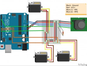 <–[Click for detailed schematic]
- If you would like to add a trigger servo motor to your design, set up the electronics in this fashion. The third servo motor gets attached to pin 11.
- The same code used above will work, you just have to uncomment the sections that are in grey by deleting the dashes.
– // or */ or /* - Now the third servo motor will quickly move one way, then back when you push the joystick down.
