Motor Control
This section will cover the basic configurations used to control a motor with a transistor.
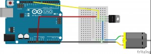
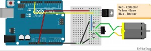
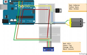
For these exercises use the blink sketch in your Arduino folder. You must change the pin used to 11, this is done by changing int led = 13; to int led = 11;. Click on the pictures for more detailed schematics
File —> Examples —> 01.Basics —> Blink
Configuration A.
Set up the following circuit. This sends a signal to the transistor to let current flow to the motor and make it spin.
A transistor works like a gate. The current “builds up” at one end of the gate (pin 1), and will not pass through to the emitter (pin 3) unless a voltage is applied to the base (pin 2). The transistor can be used to regulate the current that passes through it by applying variable voltage to the base (pin 2), but it can also just be used as a switch that can turn off and on REALLY fast (as fast as signals can be sent to the base). Transistors form a basis for all computing power!
**The transistor is not actually needed for this circuit, but it is a useful component**
Configuration B.
This next configuration allows the motor to spin in opposite directions. It might be hard to tell which way it is spinning because it is going to fast!
This circuit uses a switch and two push buttons. Power comes to the middle of the switch, which will relay the power to whichever side it is flipped to. The buttons work to complete the circuit to ground. You must push the opposite button from the way the switch is flipped or you will short the circuit and stop it’s proper functioning, but this won’t break the Arduino.
With the right combination of diodes and transistors you can set up a circuit that does not need a push button to complete. This will be left as an exercise if you feel up to it.
Sonar Control
For using the sonar only, set up only the bottom bread board in the following schematic.
Use this code to make your circuit work properly, and then to monitor distances press the serial monitor in the top right of your Arduino programming window.
#define trigPin 10
#define echoPin 8
int duration;
int distance;
void setup(){
Serial.begin(9600);
pinMode(trigPin, OUTPUT);
pinMode(echoPin, INPUT);
}
void loop(){
digitalWrite(trigPin, HIGH);
delayMicroseconds(1000);
digitalWrite(trigPin, LOW);
duration = pulseIn(echoPin, HIGH);
distance = (duration/2) / 29.1;
if (distance >= 100 || distance <= 0){
Serial.println(‘Out of range.’);
}
else {
Serial.print(distance);
Serial.println(‘ cm’);
}
}
This works by activating and sending out the sonar pulse for 1 second, then turning it off and using the pulseIn command to measure the time it takes for the sound to come back to the device. The numeric operations done on the time are pre-calibrated to give a proper measurement in centimeters.
Sonar + Motor Control
Set up the full circuit shown above and implement the following code.
int motor = 11; // Sets the pin to use for the motor control as 11
int spd = 0; // Variable for speed control
#define trigPin 10
#define echoPin 8
void setup() {
pinMode(trigPin, OUTPUT);
pinMode(echoPin, INPUT);
pinMode(motor, OUTPUT); //Sets the motor control pin as an output
Serial.begin(9600); //Starting the serial monitor for debugging
}
void loop() {
int duration, distance;
digitalWrite(trigPin, HIGH);
delayMicroseconds(1000);
digitalWrite(trigPin, LOW);
duration = pulseIn(echoPin, HIGH);
distance = (duration/2) / 29.1;
if (distance >= 100 || distance <= 5){
Serial.println(‘Out of range’);
analogWrite(motor, 0);
}
else {
spd = (distance+30)*2;
analogWrite(motor, spd);
Serial.print(distance);
Serial.println(‘ cm’);
}
delay(500);
}
Can you figure out how the motor is being controlled to go faster or slower?
PWM (Pulse Width Modulation) can be used on certain arduino pins automatically by choosing analogWrite() instead of digitalWrite(). This makes the pin turn off and on at certain speeds set between 0 – 255. 0 is off all the time and 255 is on all the time. For a complete description of pulse width modulation and a manual implementation see the LED + Potentiometer instruction set.


