Simple LED Usage
This section will cover the basic electronic configurations used to control a light, turn it off and on, and adjust it’s brightness. These are versatile techniques that can be applied to other components such as motors. For all these exercises use the blink sketch in your Arduino folder.
File —> Examples —> 01.Basics —> Blink This is a simple program that will turn pin 13 on your Arduino off and on in 1 second intervals.
1. Basics
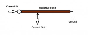
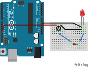
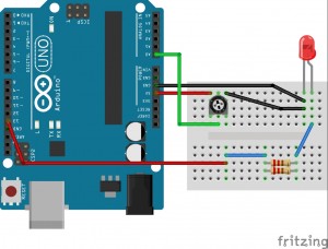
Configuration A. This connects the LED right to pin 13 on your Arduino. Be sure to connect the short leg of your LED to ground or it will not light up, as LEDs only allow current to flow through one way. The resistor is attached to ensure that you do not blow your LED. Without a resistor there is no control to the current flowing through the LED and it will burn out extremely fast. Resistors are generally used to limit current, reduce voltage, adjust signal levels, or dissipate power. 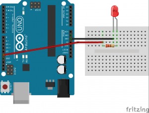 Configuration B. Let’s add a potentiometer as shown in this configuration. The potentiometer is a variable resistor that can be manipulated by adjusting the dial. The way a potentiometer works is shown below. The current enters at one side, then travels along the resistive band until it reaches the middle point. This middle point is adjustable, and the farther along the resistive band it is located, the higher will be the value of the resistance. After connecting, turn the dial back and forth to get a feel for how you can control the brightness. This is accomplished by adjusting the current. If you would like to stop the light from flashing, change the delay that leaves the pin in LOW mode to 0 in the code.
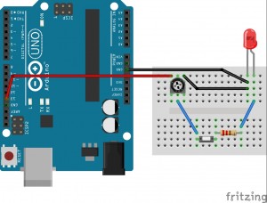
 Configuration C. Next let’s add the push button. The push button breaks the flow of current to the rest of the circuit. When the button is pushed down it closes the circuit and the light turns on! Can you think of a way to make the light turn on with one button press and off with another button press? (Hint: you will need the arduino and this is fairly difficult, this might be beyond your skills)
2. Advanced
Finally set up the configuration as shown below. We added another resistor to decrease the resistance and brighten the LED. This happens because when resistors are added in parallel they decrease the resistance, before we added the potentiometer in series to increase the resistance. We will use PWM (pulse width modulation) to adjust the brightness of the LED. Pulse width modulation is used as a way of changing a digital signal ( on/off ; High/Low ) to an analog signal ( full range of values ). This works by adjusting the time the signal is on and off ( i.e. 1 mS [millisecond] on, 1 mS off ; 1 mS on, 2 mS off ; etc.). If a computer were reading this it would average the values to read an analog signal that was between high and low. With the LED, your eye does the averaging. We cannot perceive something being turned on and off that fast so it will make it dimmer or brighter depending on the values. Using the blink sketch, adjust the delay values to single digit numbers and see what happens. Try adjusting them to be equal, then see what happens if you make it on longer than it is off, and vice versa. **Optional Challenge** Control the brightness of the LED using the potentiometer and PWM. Only attempt this if you are comfortable programming an Arduino sketch. There are a series of hints below to get this working if you are interested but lack proper experience:
- Create another integer variable for storage.
- Read the value from the potentiometer with the command analogRead(A0); and set to that variable
- Set the OUTPUT led pin to a pin that is PWM (automatic PWM) enabled, noted by the tilde and changing the code and circuit to reflect this.
- Doing some mathematic operation on the storage integer to create a number within the range of 0-255.
- Using the command analogWrite(led, variable); to turn on the light to desired brightness.
 The PWM enabled arduino pins automatically use PWM with analogWrite(); to turn the pin off and on at a frequency that ranges from being always off (0) to always on (255). This can be quite useful after understanding the basics of what PWM is really doing.