You have ~2 hours to work your way through these activities. Plan your time accordingly! Gather up some materials one used PCB (should have old components already soldered in the board) one piece stranded-core wire (black or red or green or white) one piece of solid-core wire (blue or orange or yellow or grey) one 8-pin socket about 1 foot length of solder. Clean and re-tin your solder tip Your solder iron tips should already be clean and tested, but if solder does not melt onto the tip use Solder Iron Tip Tinner (found next to the Heat Shrink Tubing) Weller tips have several coatings. Some tips are old and need just a small amount of rubbing with emery cloth to remove oxide layer, but try to avoid doing this. Watch as the rosin boils off the solder. Occasionally bubbles up enough to end up on hands and eyes. Use side cutters to trim long wires on back of PCBs. Notice how far clipped items can fly from the boards, watch out for people around you. Use 3rd Hand if necessary. Practice soldering the following: solid-core wires into the PCB stranded-core wires into the PCB (check for loose strands!) 8-pin sockets into the PCB (solder 1 corner pin first, then ensure the socket is flat on the PCB, then solder the remaining pins) put two stranded-core wires together to form one longer wire. coat one stranded-core wire with excess solder. Feel how much stiffer and more brittle the excess solder makes the wire Watch some desoldering videos Watch video of desoldering tool, Watch video of solder wick Practice some desoldering Remove 2 wires (stranded or solid) from a used PCB. Remove one BJTs. See if you can remove it without clipping the leads from the BJT or destroying the component. Get a TA/instructor to inspect your soldering and desoldering work. Watch the video to see the parts. Solder the QRD (1 for each person) Gather materials 3 pieces of stranded wire, ideally from the used wire bins You will need ~8 inches of wire length for each color. male header pins 330 ohm resistor Cut male header pins to correct number of pins. It is plastic, so you can use your side cutters. Be careful, as you may accidentally cut adjacent pins in the header and parts may fly into your face. Return extra pins to bin. Solder, hot glue, heat shrink connections For the QRD, you will be including an appropriate resistor (330 ohms) inside the QRD wire as shown in the sample and in the diagram here. Mark the resistor value on the outside with a label. Get Lab instructor / TA to inspect your connector. Solder the Motor (1 for each person) (~15 minutes) Watch the video to see the parts. Use two pieces of stranded-core wire, approximately 8inches in length. You can use the screw terminals on the TINAH motor outputs to attach the motor. Try one of each connector. Try not to waste attempts, as each connector varies in price from reasonable to not reasonable. PCBs and Wire Polarization on 8-pin socket board-to-board vs. board-to-wire connections PCBs for 253 (Boris and Natasha). End of Page.Part 1: Practice Soldering and Desoldering At Your Benchbench (~30min)
Part 2: Solder one QRD and one Motor for your tape follower (~45min)

Part 3: Check out connectors and PCBs in other room
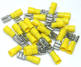
 Quick Connect Terminals
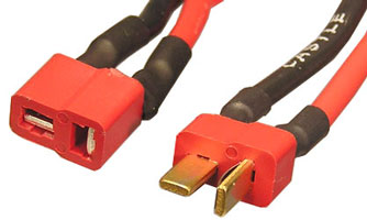
  Deans Connectons (for TINAH and battery)
 ![]() IDC connectors for ribbon cable
IDC connectors for ribbon cable MTA-100 Connectors (single-wire connections to board)
 Wire Nuts
- Home
- ProjectLab
- ENPH 479 (Fall 2019)
- ENPH 459 (Fall 2019-Spring 2020)
- ENPH 353 - 2019 Term 2
- ENPH 253 (Summer 2019)
- Guides for 459/479
- ENPH 480/481
- Info for Project Sponsors
- Available Projects
- Hennings 115
- Lab Resources
- Student Awards
- Sign-Up Page
- Jobs
- Events and Talks
- Course Archive
- APSC 278 - 2018March
- ENPH 259 - presentations (2017 Nov)
- Sign-Up Page (APSC 101)
- Arduino (CUEBC 2016)
- COMM 386p (fall 2016)
- COMM 386p (Spring 2016)
- BAEN 580B (2015)
- BAEN 580B (2014)
- BAEN 542 (2013)
- Arduino Hands-On (2015)
- APSC 150 (Feb 2015)
- APSC 150 (Sept 2014)
- APSC 150 Tut 1.4 (Jan 2013)
- ENPH 459 (fall 2014)
- APSC 150 - electronics (2013)
- APSC 150 - Hand Tools (2013)
- IGEN 230 - mini-bootcamp (2012)
- PHYS 350 - projects (2017Jan-Apr)
- ENPH 479 (fall 2017)
- ENPH 479 (fall 2016)
- ENPH 479 (fall 2015)
- ENPH 479 (fall 2014)
- ENPH 479 (2013)
- ENPH 479 (2012)
- ENPH 479 - 2011/12
- APSC 479 - 2010/2011
- APSC 479 - 2009/10
- ENPH 459 (Fall 2018-Spring 2019)
- ENPH 459 (fall 2017)
- ENPH 459 (fall 2016)
- ENPH 459 (fall 2015)
- ENPH 459 (2013)
- ENPH 459 (2012)
- ENPH 459 - 2011/12
- APSC 459 - 2009/10
- APSC 459 2010/2011
- ENPH 253 (2018)
- ENPH 253 (2017)
- ENPH 253 (2016)
- ENPH 253 (2015)
- ENPH 253 (2014)
- ENPH 253 (summer 2013)
- ENPH 253 - 2012
- Phys 253-2011
- PHYS253 - 2010
- Phys 253 2009
- MINE 432 - Fall 2014
- PHYS 350 - projects (2011/12)
- MINE 432 - Fall 2010